Table of Contents
attiny20 BGA chip reballing
Introduction
BGA (ball grid array) chips are surface mount ICs which use small solder balls on the underside of the chip to bond to pads on a PCB when heated.
I decided I wanted to learn how to remove a BGA chip, reball it, and then solder it back to a PCB. The process of reballing is required once the chip is removed because the solder balls melt and often remain on the PCB.
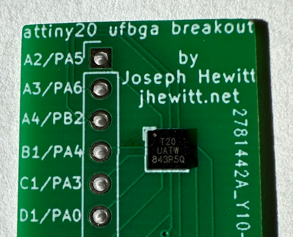
I decided to use the attiny20 in the UFBGA-15 configuration which contains 15 balls. I designed a basic breakout board for this chip and had it produced for me.
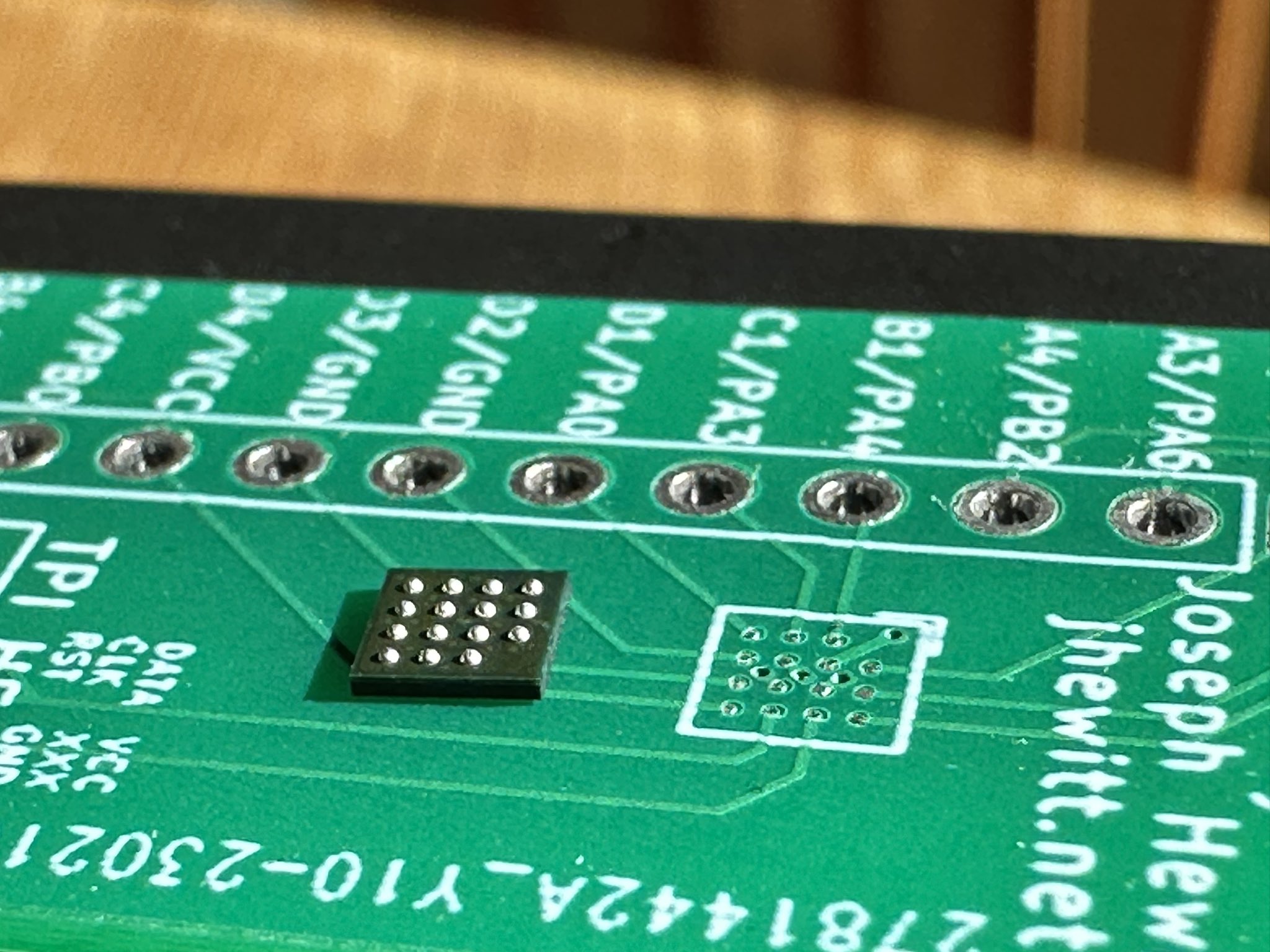
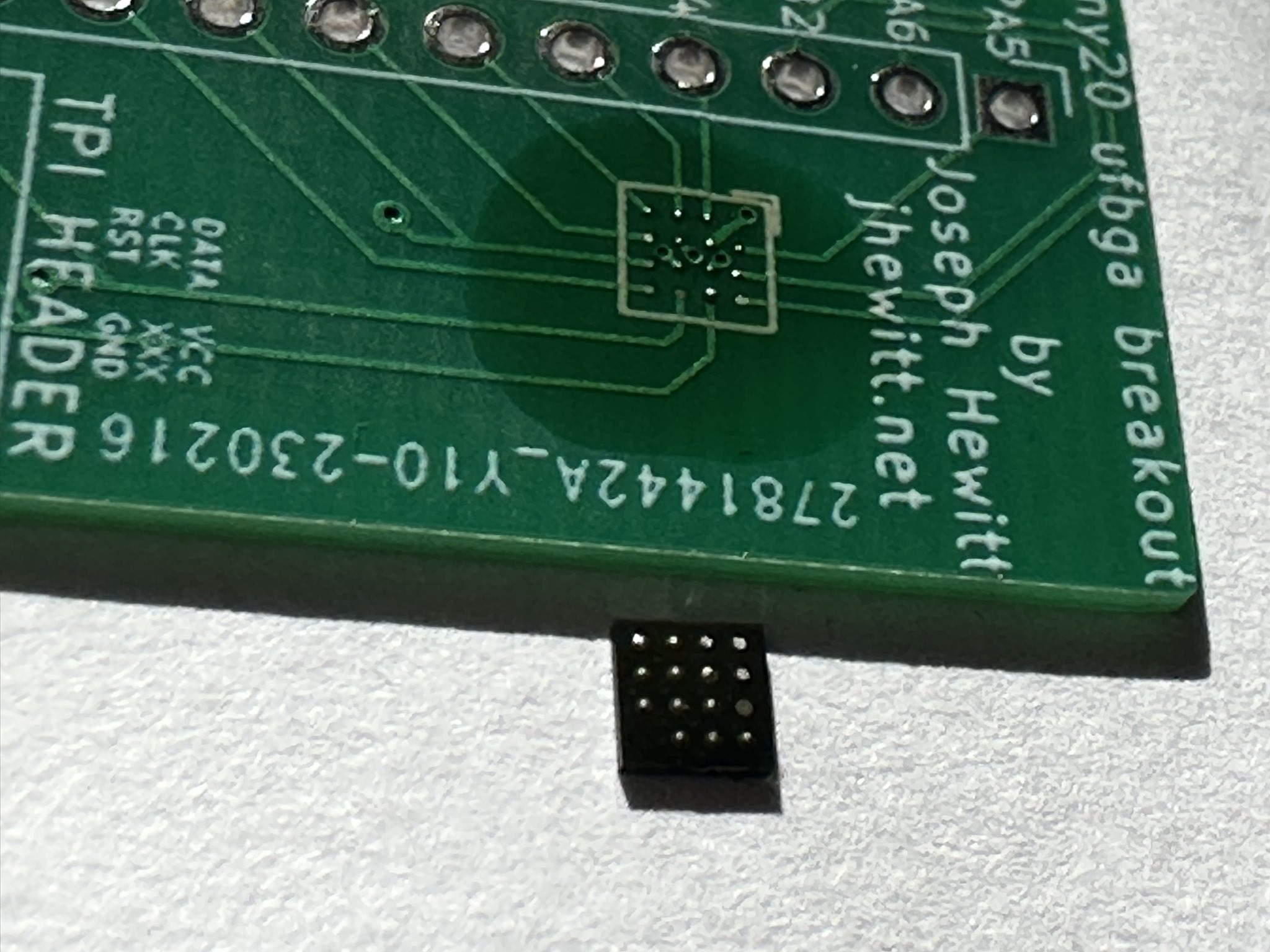
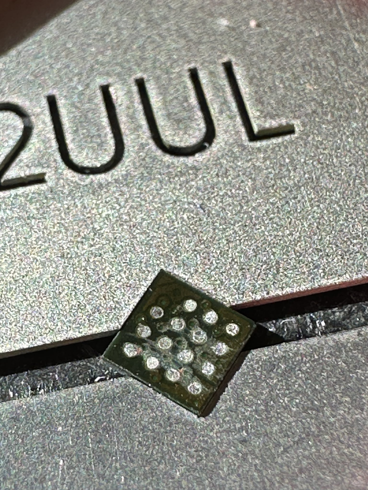
The above image shows the attiny20 resting near the pad where it will be soldered. The balls currently shown on this image are the original from the factory.
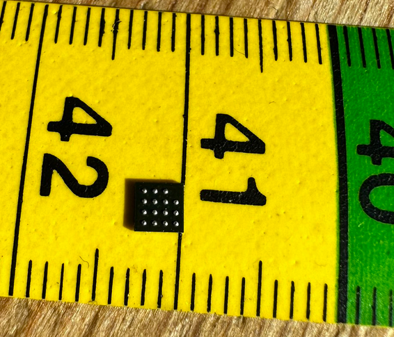
For scale, the above image shows the chip resting on a ruler. It is approximately 3mm by 3mm (0.12“ by 0.12”).
The Process
I started by soldering one of the attiny20 microcontrollers into place as normal using a hotplate.
After verifying there were no short circuits by testing the pinout with a multimeter, I heated the board again with flux and used tweezers to remove the chip.
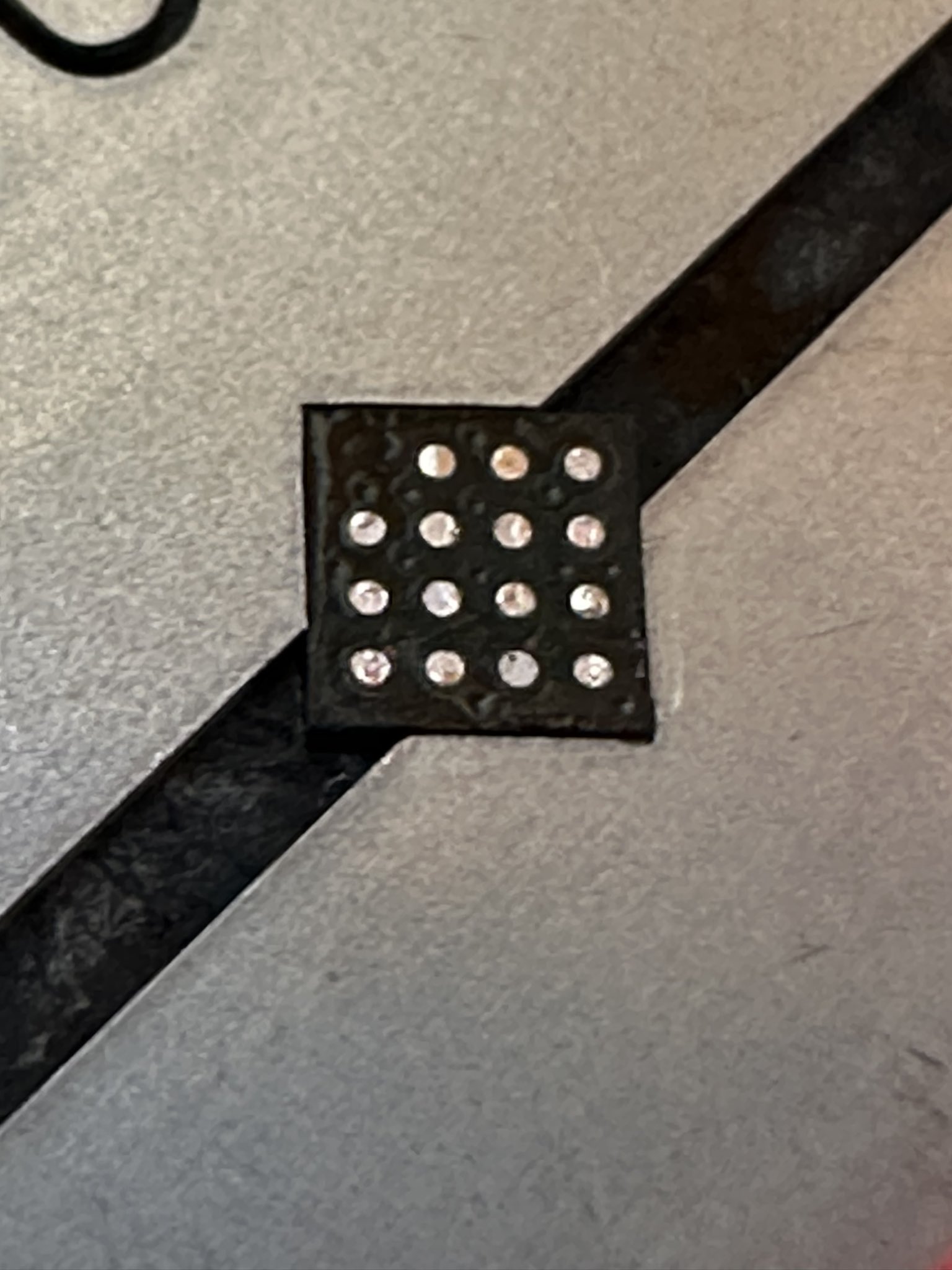
This resulted in a PCB which had excess solder remaining and a chip with no remaining balls. In order to make them usable again, both needed to be cleaned using solder wick. I used a vice to keep the chip in place while working on it. After removing all excess solder from the attiny20, it looked like this:
To make sure the new balls would stick effectively, I used IPA alcohol to ensure it was clean and then applied a small amount of leaded solder to each pad (AKA tinning the pads). I also applied a small amount of additional flux. This returned the usual shine to the pads.:
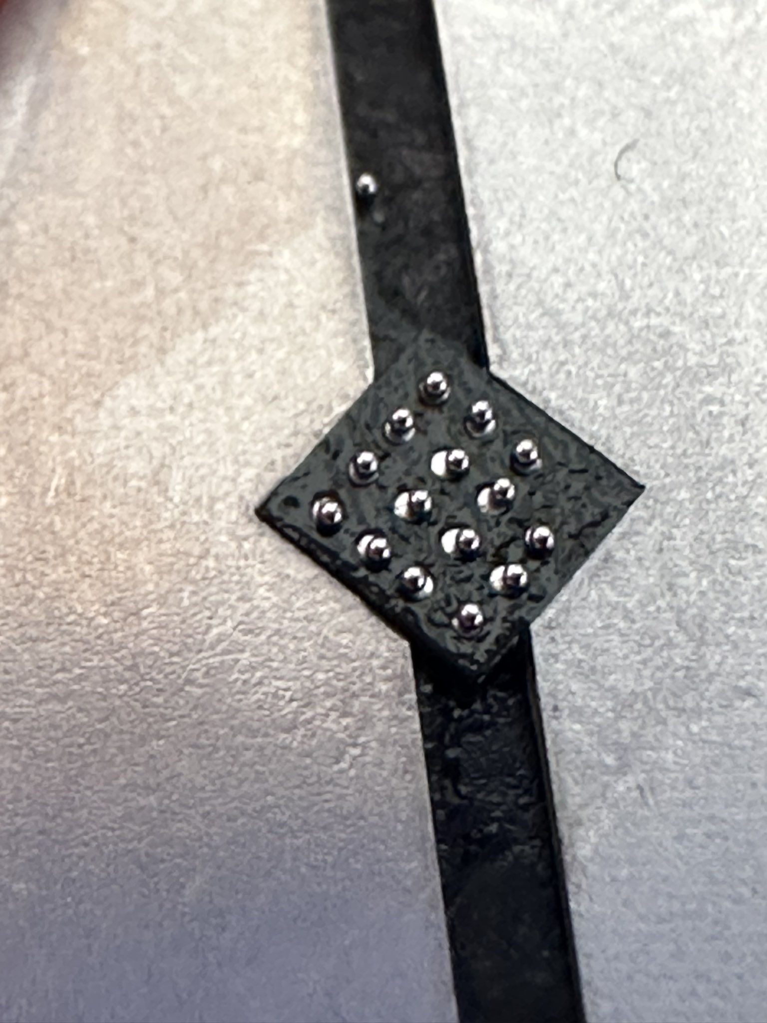
The next step is to place a solder ball onto each pad. I used more flux for this step as it is slightly tacky and prevents the balls from simply rolling away. I used very fine tweezers to nudge the balls into place. It looked like this once each pad had a ball on top:
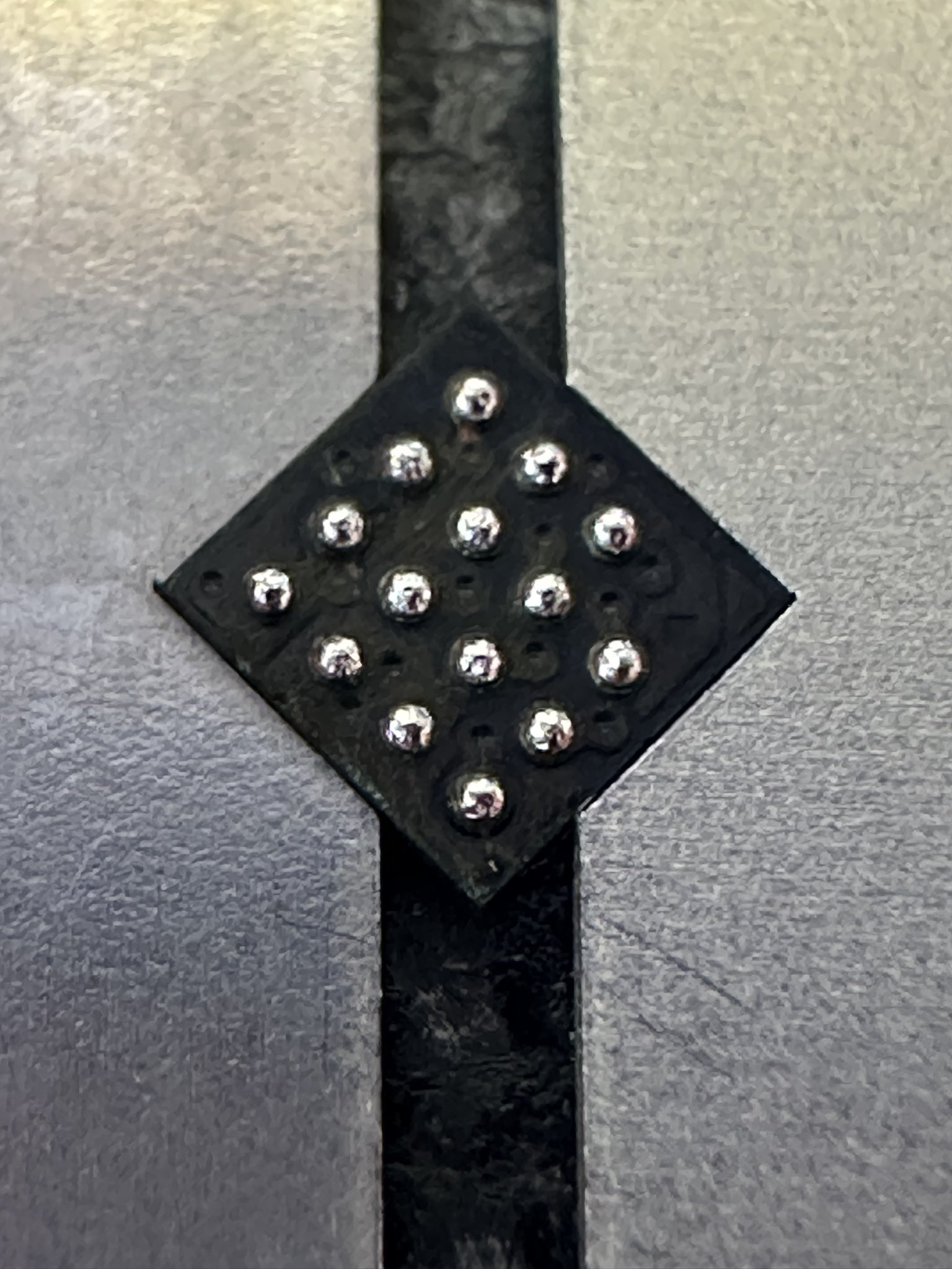
For the next step I placed the chip (with the balls facing upwards) onto the hotplate. The solder melted and flowed into the correct positions so it didn't matter that some of the balls were placed slightly out of alignment. After melting and more cleaning with alcohol, the balls on the chip looked like so:
I cleaned up the PCB and tinned the pads in a similar way to the chip. This allowed me to solder the chip in the same way I would with a “fresh” chip.

