Table of Contents
Improving Devices by Flashing Tasmota
Introduction
Tasmota is an open source project which is described as “alternative firmware for ESP8266 based devices with easy configuration using webUI, OTA updates, automation using timers or rules, expandability and entirely local control over MQTT, HTTP, Serial or KNX”.
I have a few “smart devices” which usually require constant access to servers belonging to the manufacturer of the product. I completely disagree with forced dependance on remote servers, so I will only buy the hardware if I am able to reprogram the device with any code of my choice.
This page includes a list of hardware I have flashed custom firmware (usually Tasmota) onto. I have also documented the flashing process for future reference.
Sonoff S20 Smart Plug
The Sonoff S20 is a WiFi smart plug which can easily be reprogrammed. There is a page on the Tasmota documentation website with Sonoff S20 flashing instructions. Other websites may also include instructions. I'll write a quick overview of what I did below.
Flashing Instructions
This is a list of the steps I took to flash Tasmota onto the S20, but I don't guarantee they will work for you. I don't take any responsibility for mistakes this page may contain, or mistakes you may make when attempting this. These steps apply to the UK model of the S20, but may still be relevant for US/EU variants.
First, ensure all power to the device is removed (unplug it). Never connect any smart plug to mains electricity while the plastic enclosure is open or damaged.
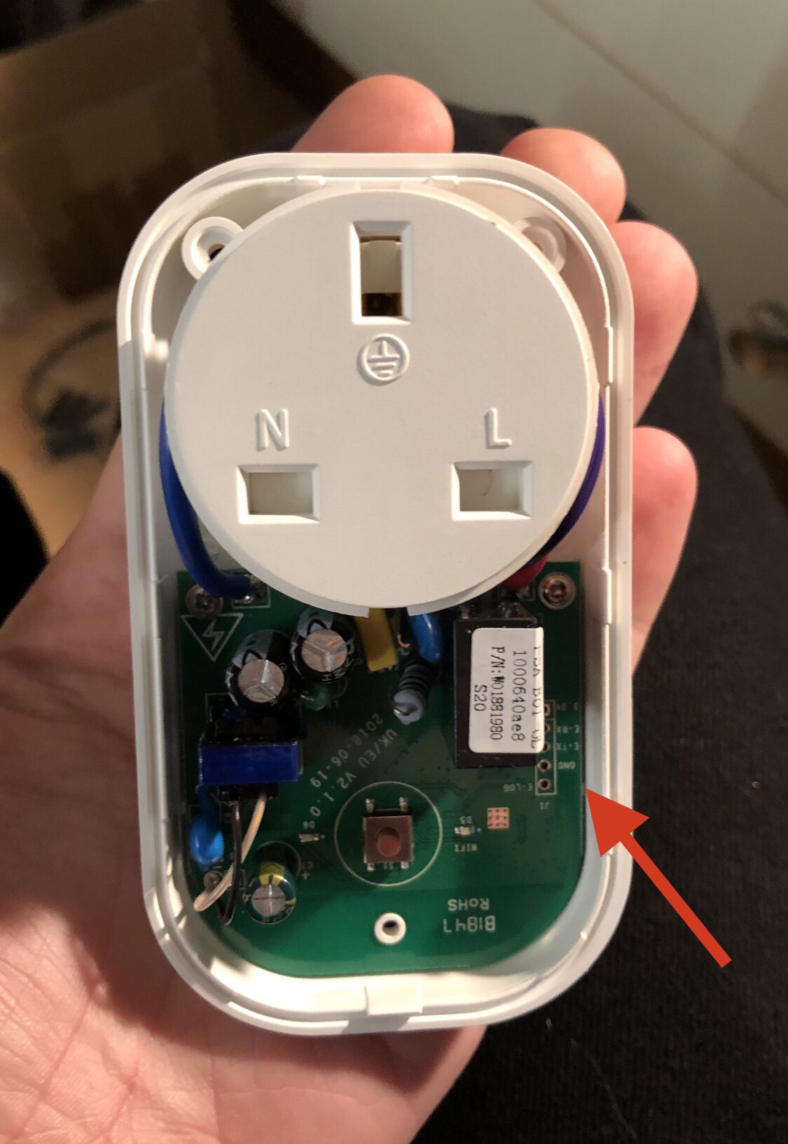
All screws need to be removed from the outside of the enclosure; check for hidden screws beneath stickers too. Once all screws are removed, the plastic enclosure should pull apart without much force. Once the enclosure is open, you should see something similar to this:
I have included an arrow in this image which shows the location of the serial pins which you will require for flashing custom code. I soldered a 5-pin header onto this part of the PCB (tip: it's much easier to solder if you separate the PCB from the enclosure by lifting it up). Be careful not to damage the high voltage wires near the plug when soldering or moving the PCB.
Once the header is in place, you can connect a USB serial adapter to the S20 using jumper wires. The wiring should match the following:
| USB Serial Adapter Pin | S20 PCB Pin |
|---|---|
| 3.3 volts | 3.3v |
| TX | E - RX |
| RX | E - TX |
| Ground / GND | GND |
| Not connected | E - LOG |
These are the only required connections for flashing. No external power is required from the mains plug.
Ensure you have downloaded Tasmota and installed esptool.py before continuing. The following instructions can also be found on the Tasmota "getting started" page
Start holding the push button in the centre of the PCB before plugging in the USB serial adapter. This causes the ESP to boot into flashing mode which is required for the next step. You need to hold the button for around 1-2 seconds, but I generally hold it for about 5 seconds to be sure.
After running each of the following commands, you may need to de-power your S20 (by unplugging the USB serial adapter). You will then need to re-do the above step (holding the push button) before performing the next command.
You can optionally backup the original device firmware with the following command:
esptool.py --port /dev/ttyUSB0 read_flash 0x00000 0x100000 s20firmware.bin
Replace “/dev/ttyUSB0” with the path to your USB serial adapter. On Windows it will be the COM port of your device, such as “COM5”. This command will create the file “s20firmware.bin” with the original device firmware. You can use this in the future to restore the original functionality of your S20.
It is recommended to erase the flash of the ESP with the following command before flashing new firmware:
esptool.py --port /dev/ttyUSB0 erase_flash
Again, make sure to replace “/dev/ttyUSB0” with the path to your USB serial device or COM port.
Finally, run the following command to actually push the Tasmota firmware to the S20:
esptool.py --port /dev/ttyUSB0 write_flash -fs 1MB -fm dout 0x0 tasmota.bin
This command assumes your Tasmota bin file is called “tasmota.bin” in the current working directory. You can replace “tasmota.bin” with “s20firmware.bin” to restore the original device firmware if required.
Tasmota should now be installed. If you power cycle the S20, you should see a WiFi network with a name containing “Tasmota”. You can then perform the Tasmota initial configuration.
Sonoff L1 Lite LED Strip
The Sonoff L1 Lite LED strip is an ESP-based RGB LED strip controller with an IR remote. I am using one of these at home but replaced the LED strip with a brighter strip from a local company.
Apparently, some other versions of this controller exist with different branding such as the “MagicHome” or “Arilux AL-LC01”. I have not tested those brands but these instructions may be relevant to them too.
Flashing Instructions
This is a list of the steps I took to flash Tasmota onto the L1 Lite, but I don't guarantee they will work for you. I don't take any responsibility for mistakes this page may contain, or mistakes you may make when attempting this.
I have heard reports that some of these devices have incompatible chips and cannot be flashed with Tasmota. My device has an ESP8285 chip which is fully compatible. You should check your chip also says “ESP8285” before attempting the flashing process.
The L1 controller is made of plastic and held together with clips. It is fairly easy to disassemble by hand or by using a flat screwdriver in the gaps of the device. Once the enclosure is opened, you also need to remove the PCB from the enclosure which is also held in with plastic clips.
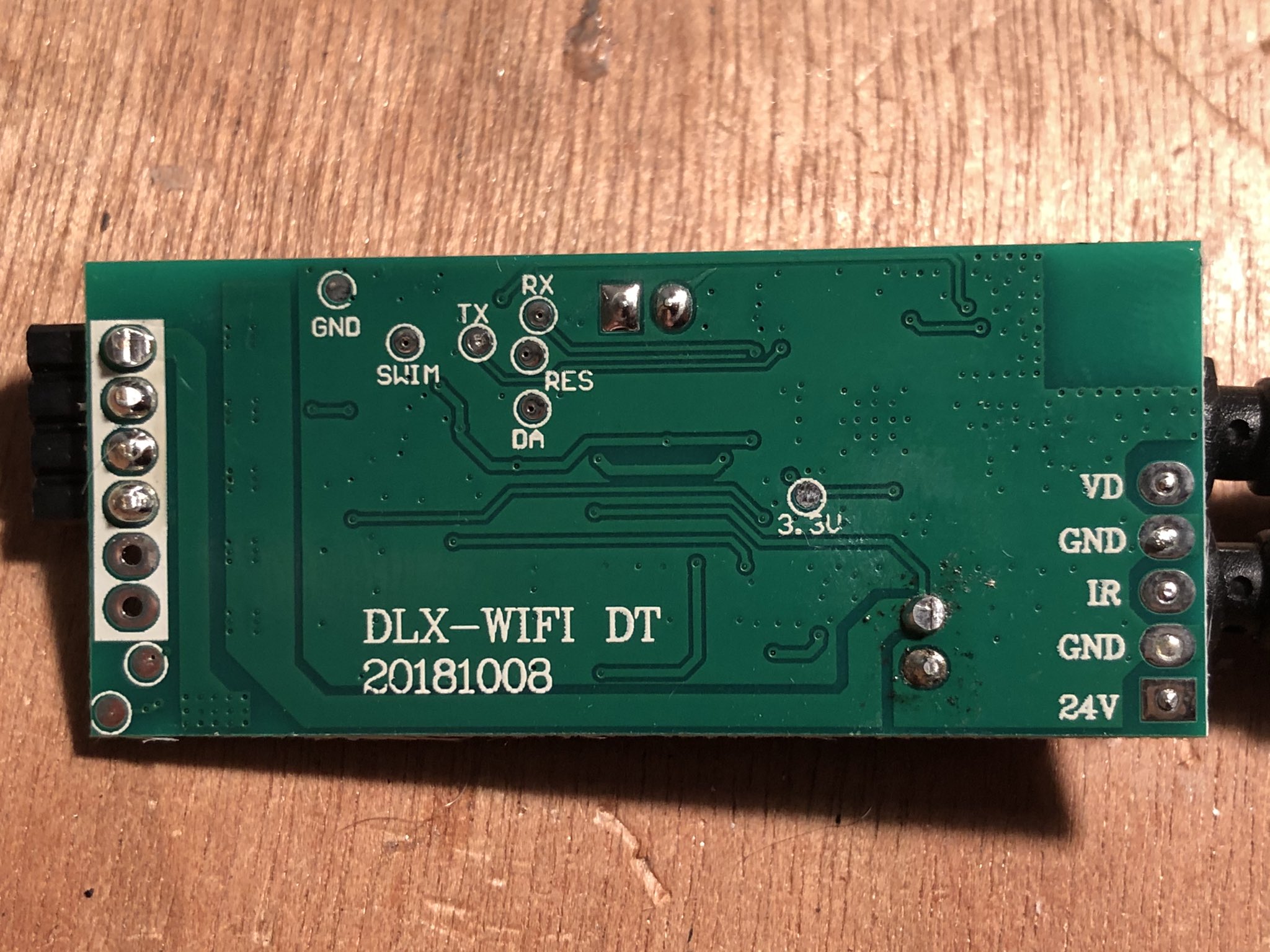
Remove the PCB and flip it over. Hopefully you will see something like this:
This specific PCB iteration is labelled “DLX-WIFI DT” and “20181008”
You need 4 connections to the PCB which are labelled “GND”, “3.3v”, “TX”, and “RX”. These 4 pads need a wire securely soldering to them which can be connected to your USB serial adapter. In a later step, you will need a second ground wire to reach the other side of the PCB. You could solder 2 wires to “GND” or make a Y-shaped wire for this purpose.
In order to interface the ESP chip with your computer, you need to make the following connections:
| USB Serial Adapter Pin | L1 Lite PCB Pin |
|---|---|
| 3.3 volts | 3.3v |
| TX | RX |
| RX | TX |
| Ground / GND | GND |
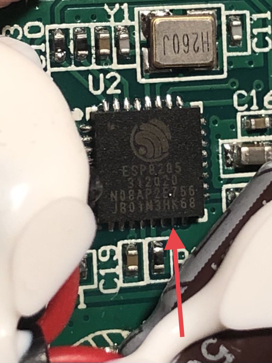
Before you are able to run any commands to flash the ESP, you need to short the GPIO0 pin of the ESP to ground during boot (this is why you need a second ground wire). I have taken a photograph of the ESP chip with an arrow to indicate which pin is GPIO0:
The Tasmota documentation also includes images showing how to identify GPIO0 on the ESP8285 chip.
With the ESP chip “the right way up” (eg, the text is readable), the required pin is on the bottom row and is 1 pin before the right-most pin; the 7th pin from the left.
Ensure you have downloaded Tasmota and installed esptool.py before continuing. The following instructions can also be found on the Tasmota "getting started" page
The flashing process should be in this order:
- Unplug the USB serial adapter (if plugged in)
- Connect all of the wires between the USB serial adapter and the PCB, as shown in the above table
- Hold a wire from “GND” on the PCB to GPIO0 on the ESP8285 chip (don't solder)
- Plug in the USB serial adapter to your computer
- Wait for at least 2 seconds, then stop touching the ground wire to GPIO0. Make sure this wire doesn't accidentally touch anything else.
- Run the flashing commands (as documented below)
Many of the commands will require you to power cycle the device after completing. This means you need to re-do all of the 6 tasks above before you can proceed with the next command.
You can optionally backup the original device firmware with the following command:
esptool.py --port /dev/ttyUSB0 read_flash 0x00000 0x100000 l1firmware.bin
Replace “/dev/ttyUSB0” with the path to your USB serial adapter. On Windows it will be the COM port of your device, such as “COM5”. This command will create the file “l1firmware.bin” with the original device firmware. You can use this in the future to restore the original functionality of your L1 controller.
It is recommended to erase the flash of the ESP with the following command before flashing new firmware:
esptool.py --port /dev/ttyUSB0 erase_flash
Again, make sure to replace “/dev/ttyUSB0” with the path to your USB serial device or COM port.
Finally, run the following command to actually push the Tasmota firmware to the L1 controller:
esptool.py --port /dev/ttyUSB0 write_flash -fs 1MB -fm dout 0x0 tasmota.bin
This command assumes your Tasmota bin file is called “tasmota.bin” in the current working directory. You can replace “tasmota.bin” with “l1firmware.bin” to restore the original device firmware if required.
Tasmota should now be installed. If you power cycle the L1 controller, you should see a WiFi network with a name containing “Tasmota”. You can then perform the Tasmota initial configuration.
Tasmota Template
A Tasmota template helps Tasmota understand your hardware. I used the following template for my L1 Lite controller:
{"NAME":"Sonoff L1 Lite","GPIO":[0,3200,0,3232,0,0,0,0,0,320,0,0,0,0],"FLAG":0,"BASE":70}
I found this template on Blakadder which contains a quick writeup on how to flash the L1 controller with Tasmota too.


